In this Fire Dynamics Simulator tutorial, you are going to learn how to properly define multiple meshes in the same FDS simulation.
Mesh Basics
All FDS calculations are performed within a domain that is made up of parallelepipedal volumes called meshes. Each mesh is divided into rectangular cells, the number of which depends on the desired resolution of the flow dynamics.
A mesh is defined by the MESH line:
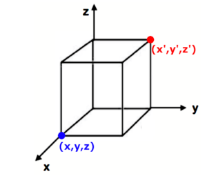
&MESH XB= x, x’, y, y’, z, z’, IJK= n(x), n(y), n(z). /
The volume is a parallelepiped defined by 2 of its opposites corners; the coordinates of the first point are x, y, z; the second ones are x’, y’, z’.
The XB command defines the dimensions of the volume in meters, in the format of XB= x, x’, y, y’, z, z’.
The mesh is subdivided into uniform cells via the parameter IJK. This parameter specifies the number of parts in which you want to divide the three dimensions (x, y, z), in the format of IJK= n(x), n(y), n(z).
It’s advisable to subdivide each mesh so that the mesh cells resemble cubes (length, width and height of the cells should be roughly the same).
Note for beginners
If you prefer a single, structured learning path that guides you step by step through FDS fundamentals and core concepts, you may want to check the FDS Fundamentals Course.
Multiple Meshes
The term “multiple meshes” means that the computational domain consists of more than one parallelepipedal volume.
Each individual mesh needs a specific MESH line.
In general, the meshes should be entered from finest to coarsest (from “smallest cells” to “biggest cells”).
Why use multiple meshes
There are different reasons for wanting to subdivide the computation domain in more than one mesh:
- reason #1: it’s sometimes useful to adopt different resolutions for different parts of a simulation (you might want to prefer fine mesh resolutions where complicated phenomena are taking place , whereas in spaces where not much is happening you probably don’t want to waste computing power, so you might want to use bigger cells).
- reason #2: you might want to subdivide the calculation on different cores/computers using MPI (see the dedicated chapter on the official FDS User Guide, this aspect is not discussed in this FDS tutorial)
- reason #3: if the case you want to simulate involves a geometry very different from a rectangular volume, in order not to waster computing power, you might want to use multiple rectangular volumes to englobe your geometry.
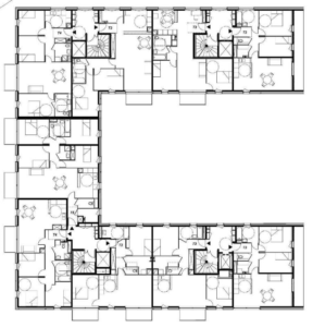
Example: imagine a fire scenario meant to be simulated in the building shown below.
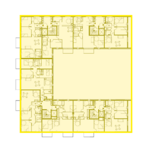
You could use a single mesh but a lot of the volume of the mesh would contain uninteresting data:
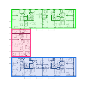
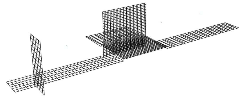
Instead, you could optimize the simulation by using 3 different meshes; in this way, you would also be able to speed up the calculation by properly adopting different MPI processes.
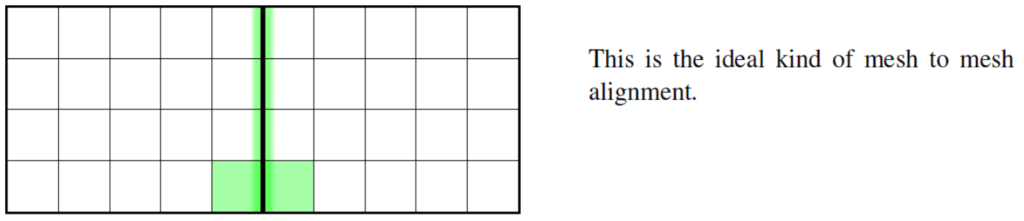
Mesh Alignment
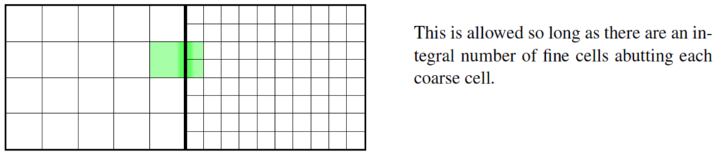
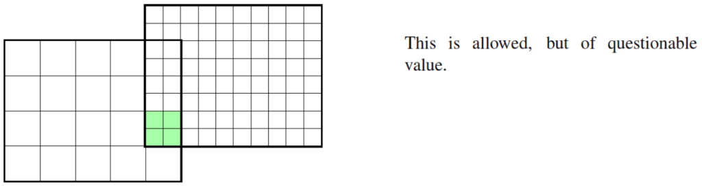
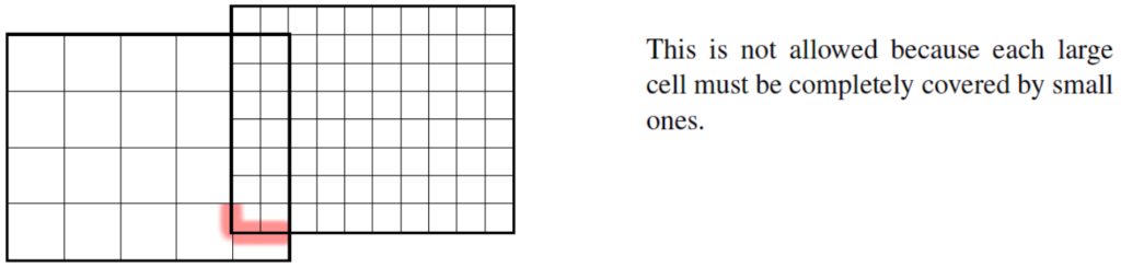
The most important rule of mesh alignment is that abutting cells ought to have the same cross-sectional area, or integral ratios, as shown in the following pictures (the pictures are taken from the FDS User Guide, but they are modified to highlight the various characteristics).

IMPORTANT TIP
The exchange of information across mesh boundaries is not as accurate as cell to cell exchanges within one mesh, so try to avoid placing mesh boundaries where complicated phenomena are expected.
Example
Let’s say we want to model a scenario in which a fire starts in a room and the smoke invades the near corridor.
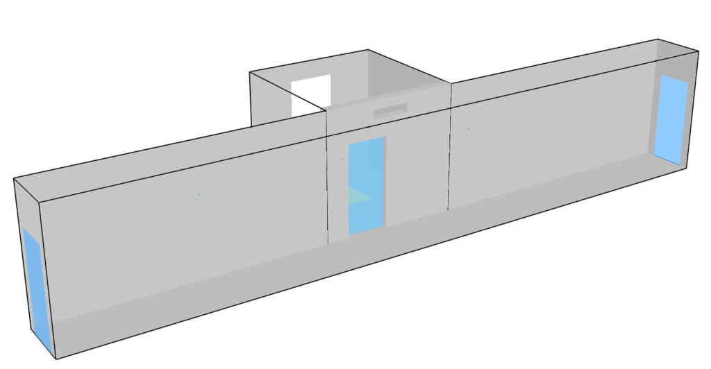
We want a refined mesh in the zone in which the smoke passes from the room to the corridor, but we evaluate that coarser meshes are suitable in the rest of the geometry.
We will use 10 cm cubes for the refined mesh and 20 cm cubes for the coarse ones, as follows:
&MESH ID='Mesh 01', IJK=30, 24, 28, XB=6, 9, 0, 2.4, 0, 2.8/ refined mesh
 &MESH ID='Mesh 02', IJK=15, 9, 14, XB=6, 9, 2.4, 4.2, 0, 2.8/ coarse mesh
 &MESH ID='Mesh 03', IJK=30, 6, 14, XB=0, 6, 0, 1.2, 0, 2.8/ coarse mesh
 &MESH ID='Mesh 04', IJK=30, 6, 14, XB=9, 15, 0, 1.2, 0, 2.8/ coarse mesh
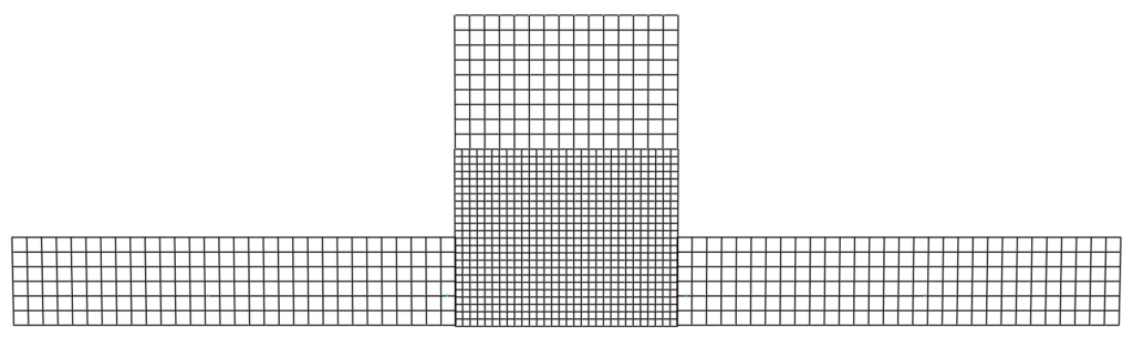
As you can see, Mesh 01 is divided with a higher resolution on all 3 dimensions:
dimension x: (9 – 6) / 30 = 0.1 m
dimension y: (2.4 – 0) / 24 = 0.1 m
dimension z: (2.8 – 0) / 28 = 0.1 m
The other meshes have lower resolution (here’s Mesh 02 for example)
dimension x: (9 – 6) / 15 = 0.2 m
dimension y: (4.2 – 2.4) / 9 = 0.2 m
dimension z: (2.8 – 0) / 14 = 0.2 m
Important things to consider
When using multiple meshes you should consider the following aspects to ensure that a simulation is properly set up:
1) The mesh boundaries should be away from areas of activity to make sure that the information is being transferred properly from mesh to mesh.
2) The user should evaluate if the loss of information caused from moving from a fine to a coarse mesh is tolerable.