In this short tutorial you will learn how to model simple supply and exhaust vents.
1. Geometry and duration
In this example we will model an exhaust and a supply vent in a 3 m x 4 m x 3 m room:
&MESH XB= 0, 3, 0, 4, 0, 3, IJK= 30, 40, 30 /
The duration of the simulation will be 60 seconds.
&TIME T_END=60. /
&DUMP NFRAMES=60 /
2. Combustion
The combustion will be simulated by giving a HHRPUA to the surfaces of an obstruction:
&OBST XB= 1.3, 1.7, 1.8, 2.2, 0, 0.5, COLOR='RED', SURF_ID='fire1' /&SURF ID='fire1', HRRPUA=150 /
The reaction parameters used are the following:
&REAC ID = 'propane reaction', SOOT_YIELD=0.03, CO_YIELD=0.05, FUEL='PROPANE'/
Note for beginners
If you prefer a single, structured learning path that guides you step by step through FDS fundamentals and core concepts, you may want to check the FDS Fundamentals Course.
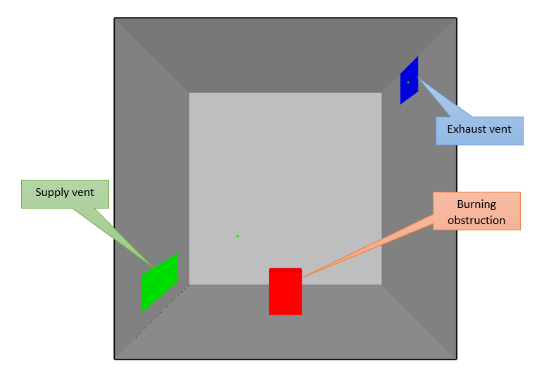
3. Supply and Exhaust vents
We want to model a supply vent in the bottom left of the room and an exhaust vent on the top right.
- The position of the vents is defined by the usual XB parameter with the format x1,x2,y1,y2,z1,z2 (depending on where you are placing the vent, a pair of these values have to be equal since the vent is flat).
- The VOLUME_FLOW parameter defines the volume flow of the vent in mc/s. If the flow is entering the computational domain, VOLUME_FLOW should be a negative number, otherwise it should be positive.
Supply vent
&VENT XB=0,0,1,3,0.2,0.6, SURF_ID='supply'/
&SURF ID='supply', VOLUME_FLOW= -1, COLOR='GREEN' /
Exhaust vent
&VENT XB=3,3,1.5,2.5,2.6,3, SURF_ID='exhaust'/
&SURF ID='exhaust', VOLUME_FLOW=1, COLOR='BLUE' /
3.1. Air velocity
Note that instead of specifying the VOLUME_FLOW, you could specify the air velocity with the parameter VEL, expressed in m/s, as follows:
&VENT XB=0,0,1,3,0.2,0.6, SURF_ID='supply'/
&SURF ID='supply', VEL = -2, COLOR='GREEN' /
&VENT XB=3,3,1.5,2.5,2.6,3, SURF_ID='exhaust'/
&SURF ID='exhaust', VOLUME_FLOW=4, COLOR='BLUE' /
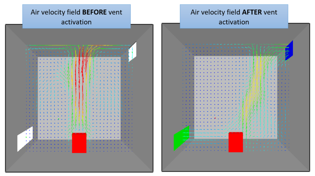
3.2. Controlling the activation of the vents
You can control the activation of the vents using basic control actions (see also “Remove obstructions during a simulation in FDS).
Suppose you want the ventilation system to activate after 20 seconds from the start of the simulation.
You can do that by:
- creating a “timer device”
- assigning that device to the 2 vents, as follows:
&DEVC ID='timer', QUANTITY='TIME', XYZ = 1,1,1, SETPOINT=20, INITIAL_STATE=.FALSE. /
&VENT XB=0,0,1,3,0.2,0.6, SURF_ID='supply', DEVC_ID='timer'/
&SURF ID='supply', VOLUME_FLOW= -1, COLOR='GREEN' /
&VENT XB=3,3,1.5,2.5,2.6,3, SURF_ID='exhaust', DEVC_ID='timer'/
&SURF ID='exhaust', VOLUME_FLOW=1, COLOR='BLUE' /
The INITIAL_STATE=.FALSE. parameter indicates that the vents are not active at the beginning of the simulation.
When the device reaches the setpoint of its quantity (in this case 20 seconds of the TIME quantity) it changes the state from .FALSE. to .TRUE., activating the vents.
Note for beginners
If you prefer a single, structured learning path that guides you step by step through FDS fundamentals and core concepts, you may want to check the FDS Fundamentals Course.
One reply on “Simple Supply and Exhaust Vents”
[…] supply and input VENTs are entered as follows (see this FDS tutorial for a complete description of the parameters that regulate the input and extraction […]